How to plan Wi-Fi for a large villa
By Zentrum Middle East · 29 August 2026 · 8 min read
For homeowners, designers and villa project teams
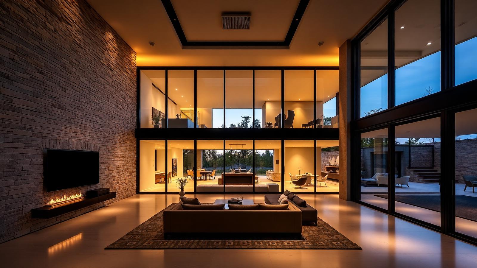
Start with the floor plan and the construction, decide access point positions from that, and cable to each one. Villa Wi-Fi problems are almost always placement and backhaul problems, not equipment problems.
Read the floor plan before choosing anything
A large villa is not a big apartment; it is several distinct zones separated by structure. Wings, split levels, basements, roof terraces, guest annexes, staff areas and gardens each behave differently. Mark on the plan where people actually spend time, where they move between, and which areas need connectivity but rarely get considered — plant rooms, garages, gatehouse, pool equipment.
Construction materials matter more than product claims
Reinforced concrete slabs, block walls, stone cladding, marble, metal-framed glazing and mirrored surfaces all attenuate or reflect wireless signal. Villas in the UAE are typically built from exactly these materials. A router advertised as covering a given area assumes open space; in a stone-and-concrete villa that figure has little meaning. Materials are the reason coverage must be planned per zone rather than per square metre.
Wired backhaul is the real decision
Each access point should have a cable back to the central rack. Wireless mesh links exist and can rescue a retrofit, but they consume airtime and their performance depends on the very walls that caused the problem. On a new build there is no good reason to rely on them: the cable is inexpensive during first fix and permanent afterwards.
Access point placement
- Ceiling-mounted, central to the area served, rather than tucked into a corner or a cupboard.
- One per zone as a starting point, adjusted for walls, levels and how the space is used.
- Coordinated on the reflected ceiling plan with lighting, sprinklers and detectors.
- Not inside joinery, behind mirrors, or above a metal-lined ceiling detail.
- Stairwells and double-height voids treated deliberately, since signal travels vertically in ways plans do not show.
Coverage versus capacity
Coverage is whether a device sees the network. Capacity is whether it performs when eight other devices in the same room are also active. A villa with a large family, staff, guests and a house full of connected equipment is a capacity problem dressed as a coverage problem. More access points at lower power usually beats fewer at high power, because each one then serves a smaller, better-defined area.
Outdoor areas
Gardens, pool decks, majlis, terraces and driveways can be covered, but only if they are in scope early. Outdoor coverage needs weather-rated equipment, a cable route out of the building and coordination with landscaping. Deciding after the hardscape is laid usually means accepting whatever spills out from indoors.
Roaming and equipment location
Consistent configuration across all access points lets a device move through the house without dropping — a single network the user never thinks about, rather than several networks they have to choose between. All of it terminates in a central rack, which needs ventilation, power and accessible space. That cupboard is where future upgrades either become simple or become a project.
Planning for change
Households change: a study becomes a nursery, an annexe becomes an office, an outdoor area gets used year-round. Spare cable runs to plausible future positions, spare switch ports and spare containment capacity cost very little during construction and preserve the ability to adapt without disruption. Performance in any specific room depends on the final construction and the devices in use, which is why the plan should be verified on site rather than assumed.
Related systems
Zentrum designs and installs wireless and network infrastructure for residences across the UAE.
System view · conceptual
Coverage planned from the plan, not the product
- 01 /
The building fabric
Concrete cores, block walls, glass and metal decide where signal actually goes — before any hardware is chosen.
- 02 /
Wired infrastructure
Cabling, containment and PoE capacity reaching every position an access point may need to occupy.
- 03 /
Access-point positions
Positions set by the plan and the ceiling detail, coordinated with lighting, sprinklers and the interior.
- Interior
- Circulation
- Outdoor
- 04 /
Coverage
Signal reaching the spaces people use, including stairs, lifts, terraces and back-of-house areas.
- 05 /
Capacity
Enough throughput for the number of devices in a room at once — coverage and capacity are not the same problem.
- Device density
- Throughput
- 06 /
Roaming
One network name and a clean hand-off as people move between floors, buildings and outdoor areas.
Outcome /
Wireless that behaves the same in every room.
Conceptual only — real coverage is set per project against the drawings and the materials in the build.

From perspective to project
Working on something where this matters? Tell us the project stage and we will tell you what needs deciding next.
Discuss a project